Dyna DM3000 Lathe Acorn Conversion
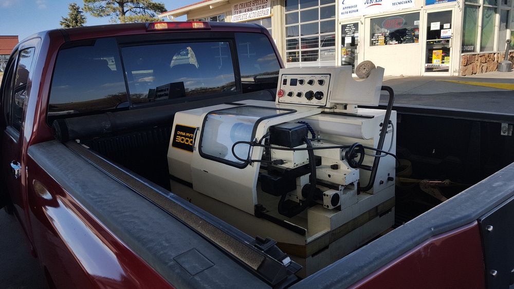
I acquired a Dyna DM3000 CNC lathe that had a pretty much completed Acorn Controller installed. Most of the wiring was completed and the conversion to Clear Path motors was finished. Just lots of piddley stuff to finish up. The documentation here will be a mix of the original person's work (Dan B.) and mine.
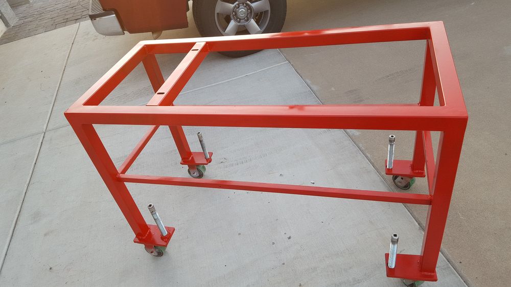
The lathe as it arrived to Dan's house. Dan made a nice sturdy rolling stand to put the lathe on. Each leg has a screw jack to support the machine. I made some rubber based isolators from aluminum discs that the screws ride on top of.
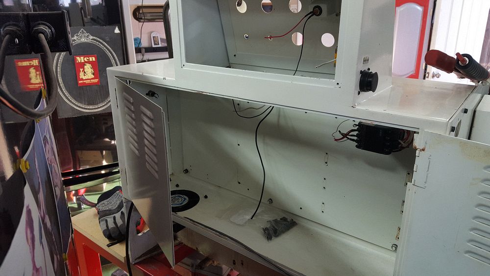
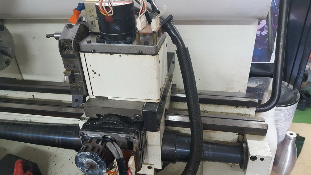
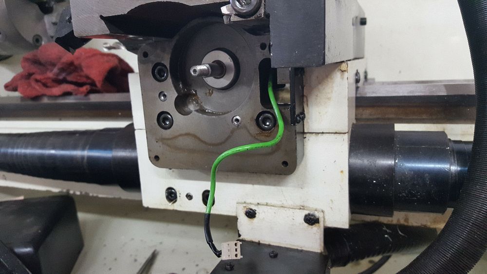
First order of business was to gut the original controls to make room for the Acorn setup. Here is the original X Axis drive motor and mounting. The stepper on the top is for the six position tool changer
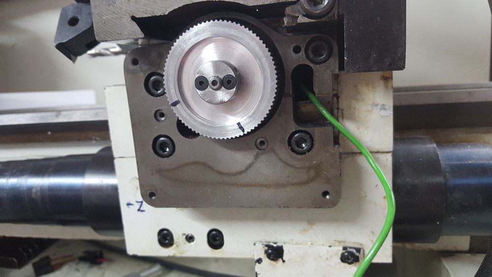
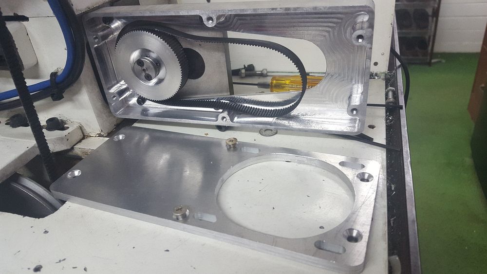
All the old parts were removed and then a drive gear was machined and installed.
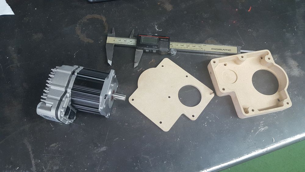
Dan machined a MDF housing and cover for testing. The new Clear Path motor is shown. The housing and belt ready for the motor.
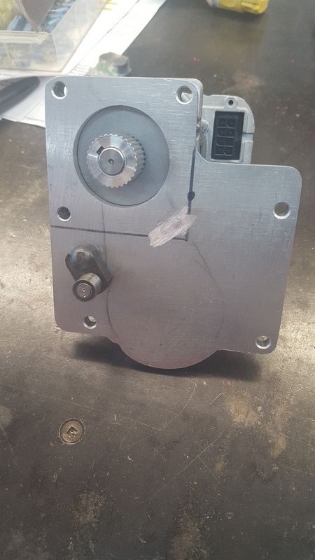
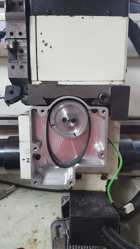
Back side of the X axis motor assembly showing the tensioner arm and motor shaft gear. Final assembly of the X axis drive.
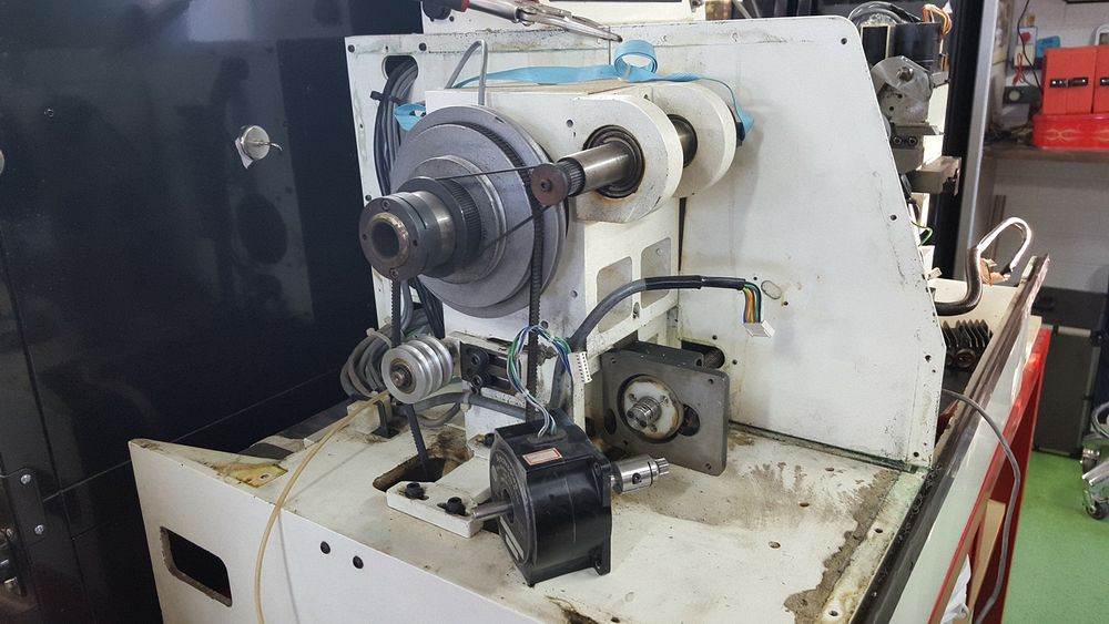
The original Z axis motor being removed. A similar housing to contain the timing belt drive and mount the motor is shown on the right.
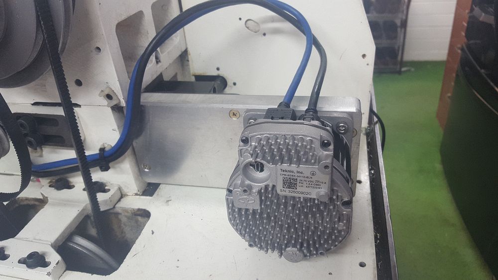
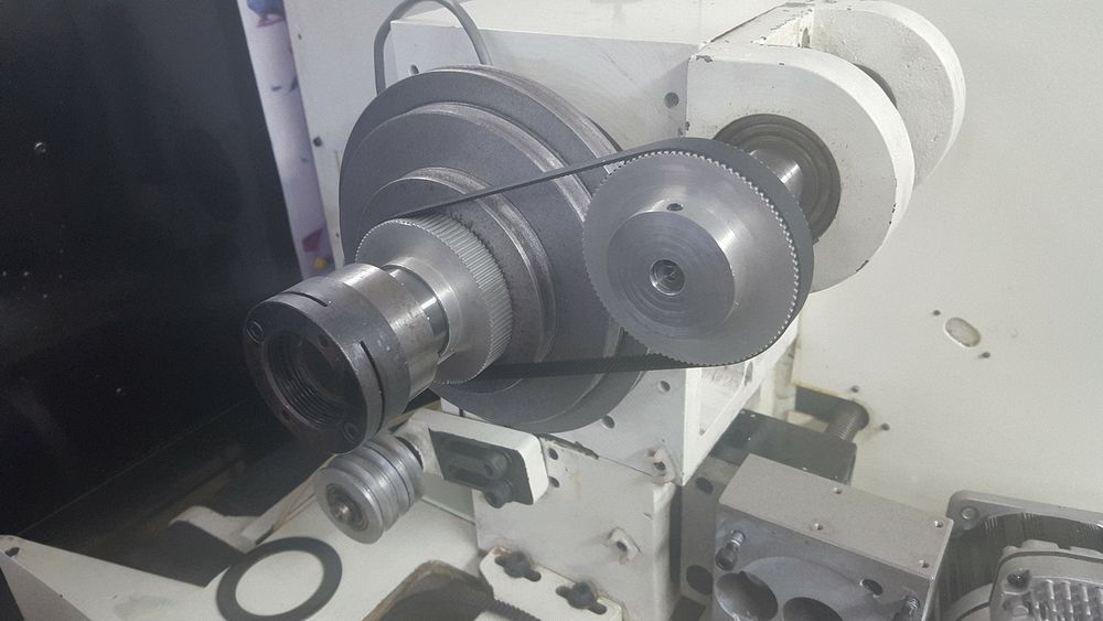
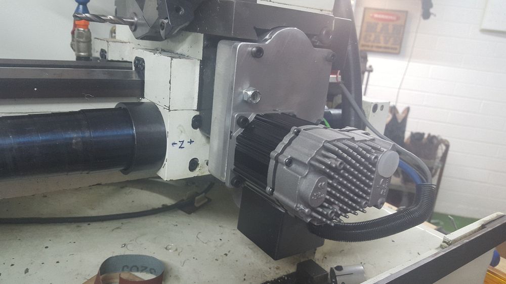
Clear Path motor for the Z axis mounted. Spindle encoder drive shown. A new belt with the correct ratio sprockets was made to fit.
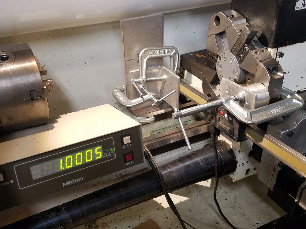
Next up was to set the turns ratio of the machine. I have a Mitutoyo 12" digital scale and readout box. The head was clamped to the turret and the foot of the scale was clamped to a plate fastened to the bed of the machine. You can never be too wealthy or have too many C Clamps...
I finally got it to the point where a 2.00" command would oscillate between 1.000" or 1.0005" Needless to say I was quite pleased. While the accuracy of the subsequent parts is pleasing, I plan to use a test bar and a dial indicator to verify how precise it really is.
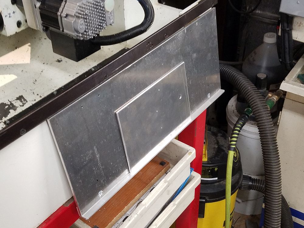
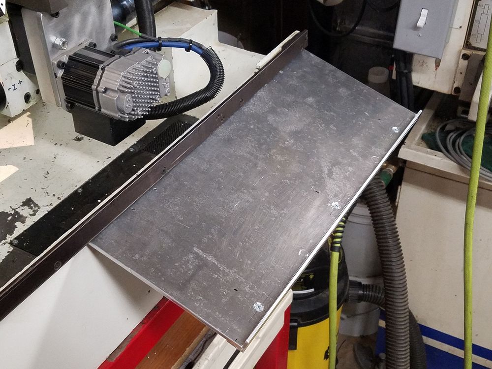
I added a folding keyboard tray. The small plate is the prop until I make a hinged support. On the right you can see the tray opened ready for use. A magnet was bolted to the back of the brace so it could be stored behind the tray on the face of the lathe housing.
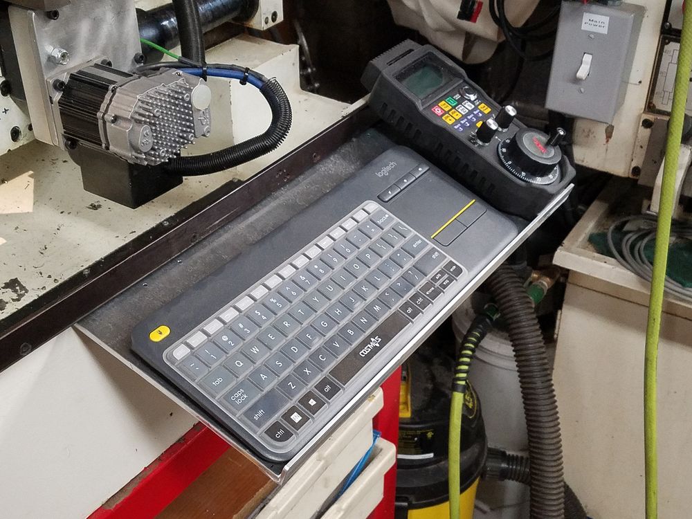
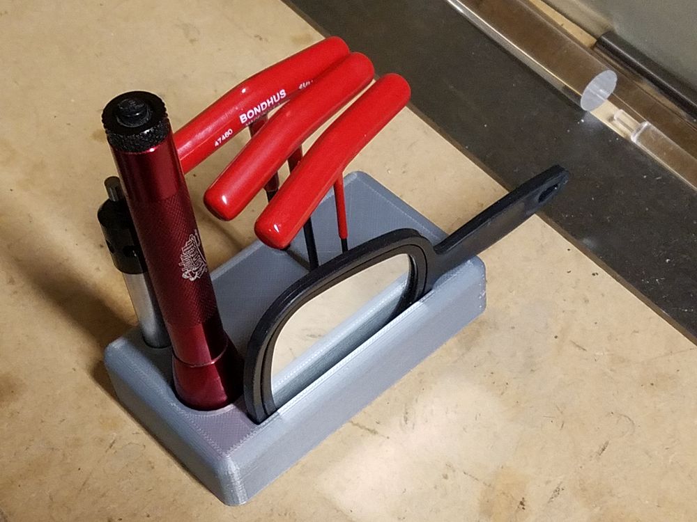
Here is the keyboard tray in use. I have found that having the keyboard on the right works better for me, leaving the Wireless MPG more conveniently located. I also 3D printed a caddy for the most used tooling for the lathe. Nicely holds the electronic edge finder, 2.5mm through 4mm Allen wrenches, inspection mirror and a flashlight.
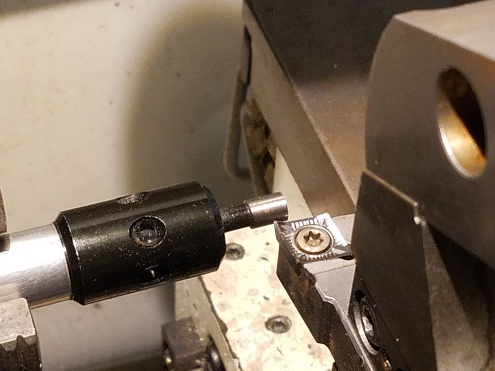
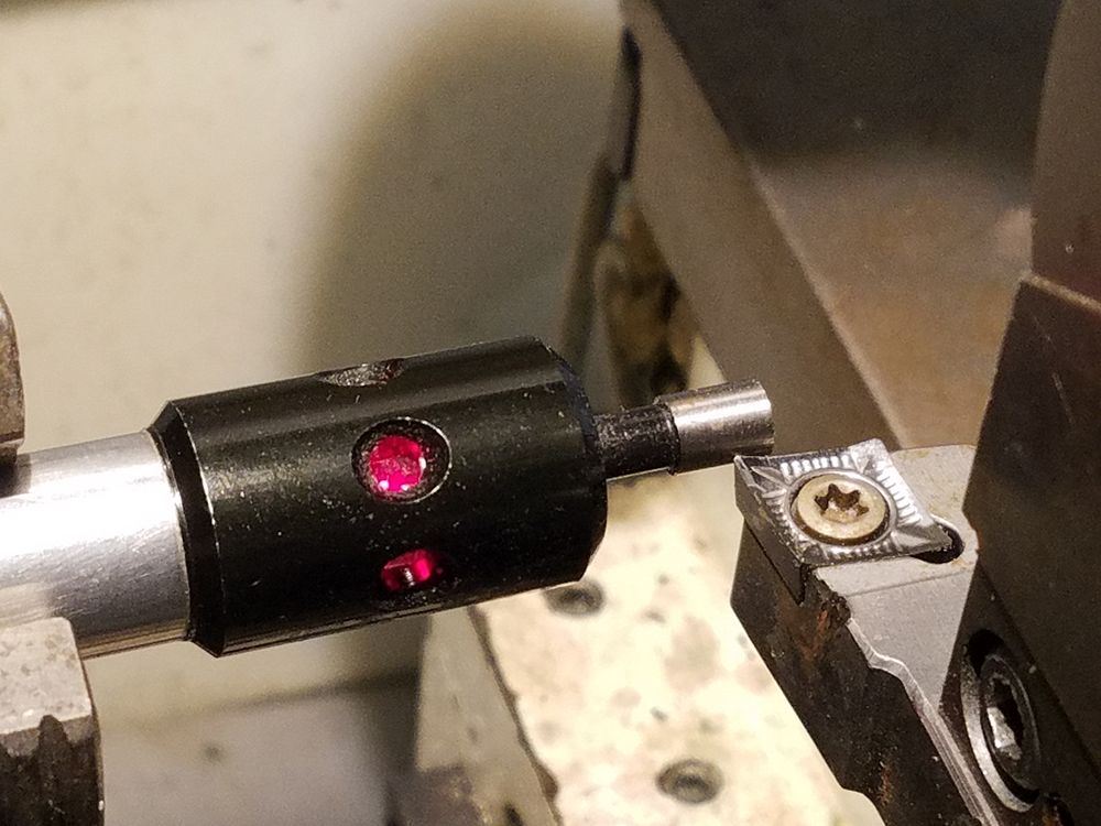
I had an electronic tool setter and decided to try this for setting up the tools. The diameter of the tip is 0.200" and this makes for easy set up of the tools. While not as precise as turning a part and then measuring, it would be good for typical work.
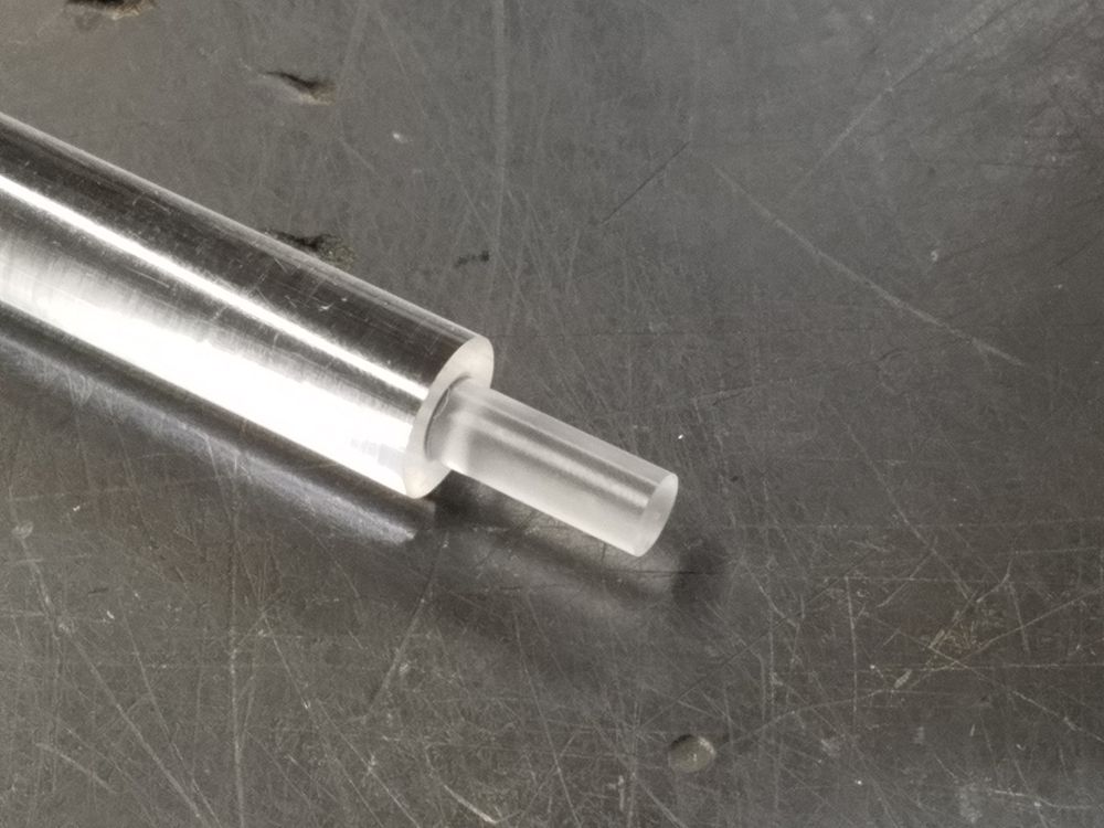
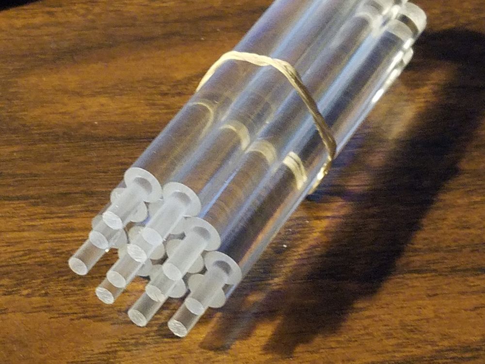
Time to make a test part. Plastic was selected for two reasons. First off, I needed to make a bunch of them for a friend and secondly I could crash on plastic with little damage other than a bruised ego.
7/3/2021
Here is a short video of the test run: https://www.youtube.com/watch?v=6fw7zF1RjGo
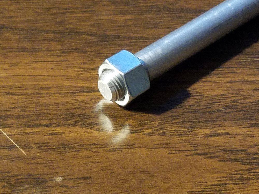
A test of threading came next. The nut fit very well with little play and turned nicely on the part.