CNC Router Project
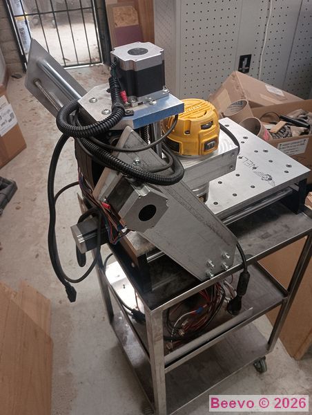
I was gifted the beginnings of a CNC Router and decided to complete it using the Smoothie Board V1 that I had sitting on the shelf. I have two other machines running this type of board and have been happy with the results and ease of setup. Both the K40 Laser and the Wanhao 3D printer have run flawlessly for years on this board.
The machine came mechanically complete and has a set of driver modules and a 36VDC power supply. It is equipped with a DeWalt 1 1/4 hp Variable Speed router motor.
Sturdy construction, the thinnest AL Plates are 1/2".
Specifications:
Travels are:
X 11"
Y 13"
Z 3.5"
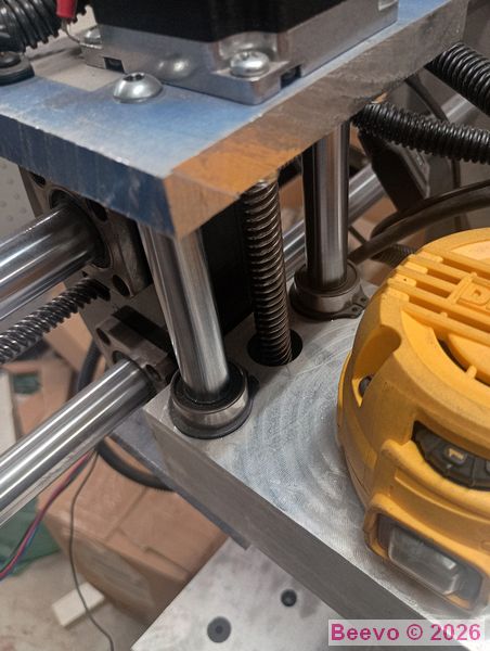
19mm linear rails
13mm lead screws on the Y and Z axis
10mm on X
Bed:
12" x 18" (X and Y)
3/4" thick
Fully Drilled
5" Clearance Collet to Bed
NEMA 23 Steppers at 36vdc
DeWalt DWP611 Router Motor
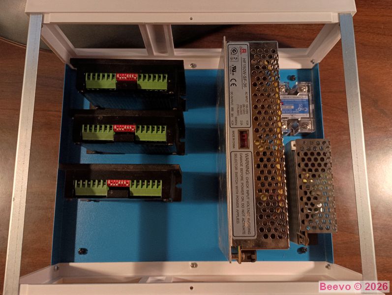
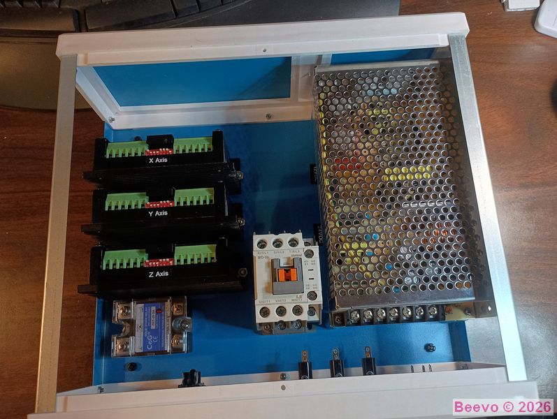
The first step was to figure out where everything needed to go. Between the 36V Power Supply and the three driver modules and THEN add a large E Stop relay it was getting full. I needed two more power supplies (12V and 24V). The 36V power Supply tipped on it's side did not allow for much if any airflow with the cover installed so I elected to mount it flat sitting up off the floor on legs and tuck the two remaining power supplies underneath. There was then enough open space above all the power supplies to keep everything cool. I 3D printed the legs and installed M3 brass inserts to thread the hardware into.
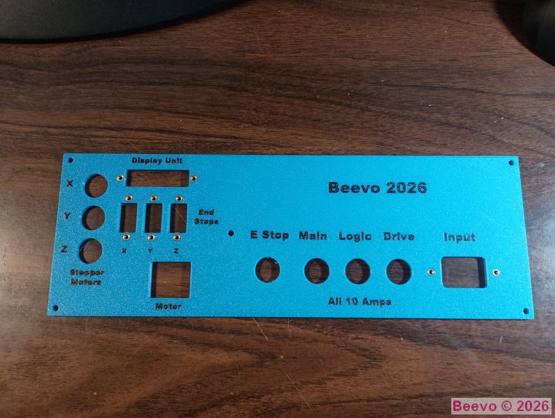
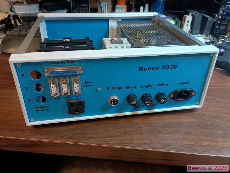
I got a nice cabinet from Amazon and decided to 3D print the front and rear panels, much easier than milling the openings and if I change my mind I have not ruined the plate. Yes, I ultimately changed my mind. I happened to have a roll of Overture Space Blue PETG filament that is an awful darned close match to the painted metal of the cabinet. Using my recently acquired Bambu Lab H2C I laid out the panel with embedded text and printed it at 0.125" thick. The three GX16-5 circular connectors for the stepper motors need to be installed. Being able to embed nice looking text in the plastic really makes for a nice end result.
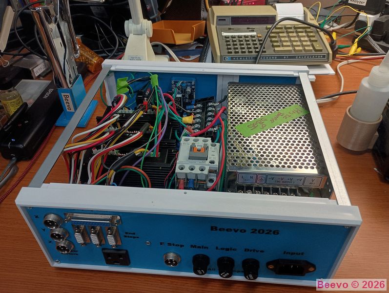
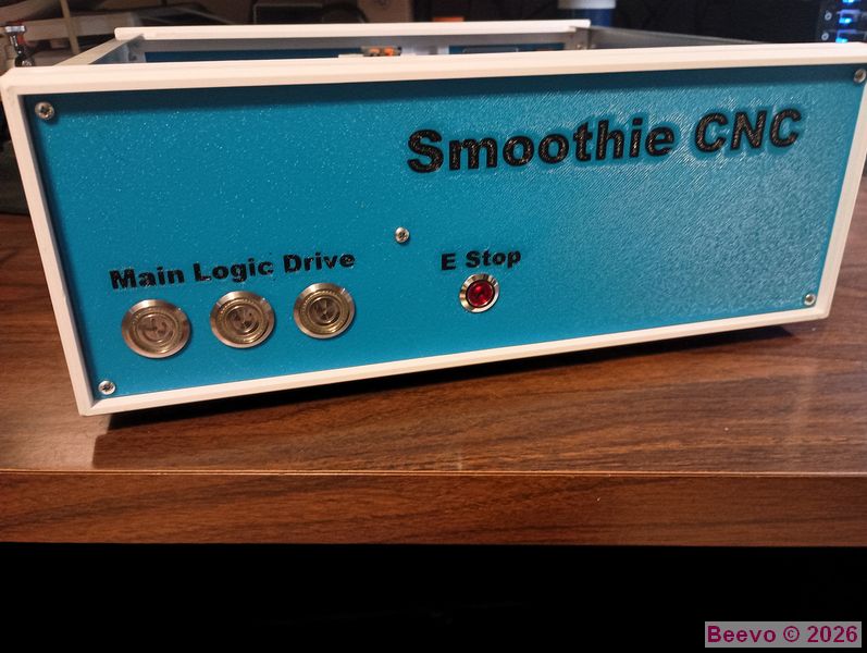
Completed power supply box Rear and Front views.
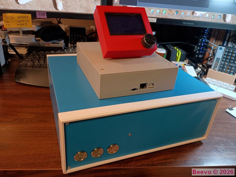
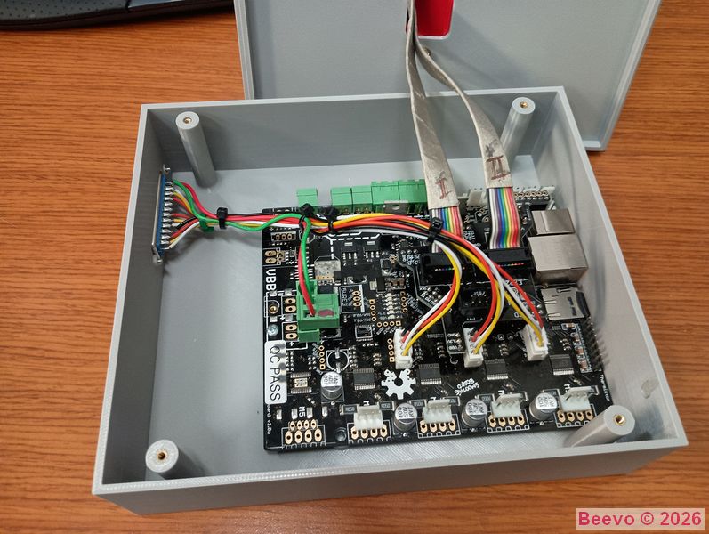
I decided to use a Smoothie Board V1 that I had in my collection of stuff. It was a spare for the Wanhao D6 and K40 Laser conversions but is not needed as both machines have been running flawlessly for many years. I 3D printed a housing for the GLCD unit (red) and the Smoothie itself. The partially wired Smoothie shown on the right. The Display Unit and Power Supply units are connected with a straight through DB25 extension cable.
Finishing the mechanical/electrical parts of the router itself consumed about a week of time. Mostly making brackets for the Proximity Sensors and cable routing.
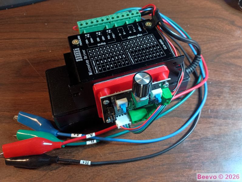
To test the axis movements while setting up the brackets and trigger blades for the Proximity Sensors, I used a spare stepper driver module that was driven by a small stepper controller I sourced from (where else?) Amazon. Because I was moving things around early on I went with the clip leads that were color matched to the lead on the motors. Right button is the Motor ON/OFF and the left button is the Reverse/Forward toggle. Pot changes the speed. Of course I had to use the 3D printer and the red bracket mounts the controller on the side of the Driver which is 3M taped to the top of an old lap top power supply.
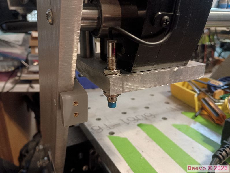
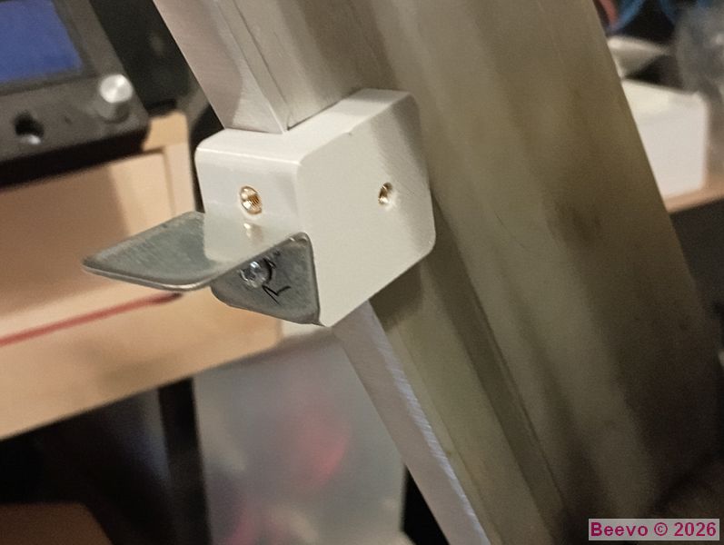
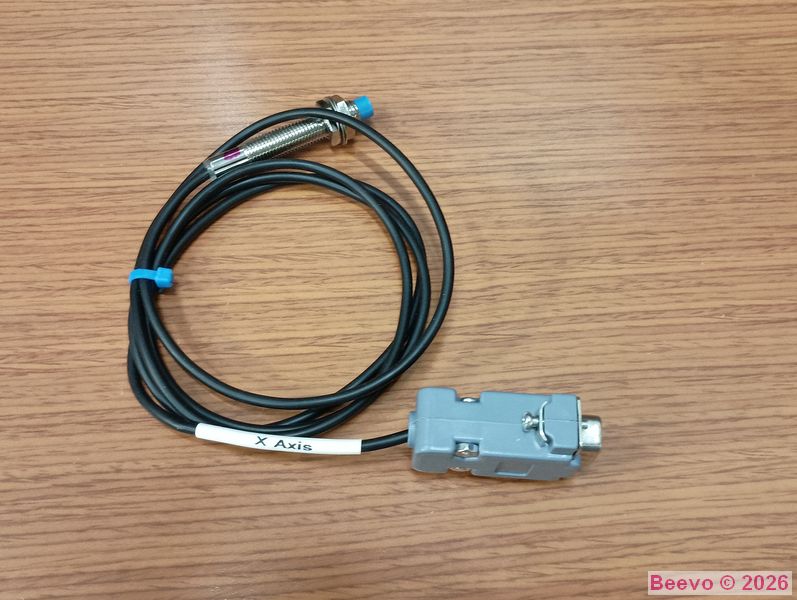
X Axis Proximity Sensor installation and trigger blade. Pretty much all the added brackets and sure were 3D printed using PETG.
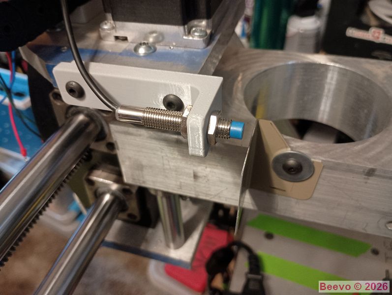
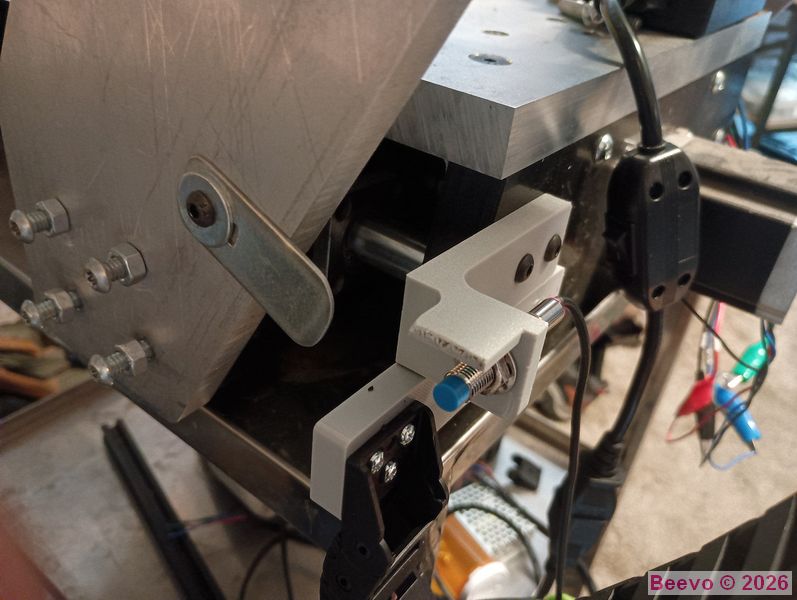
LH image shows the Z Axis sensor ant temporary trigger blade installed. RH image is the Y Axis. Once these were finished and the wiring started to get routed I embarked on routing cabling and making it neat.
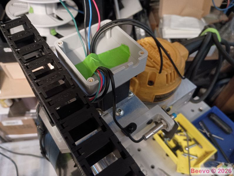
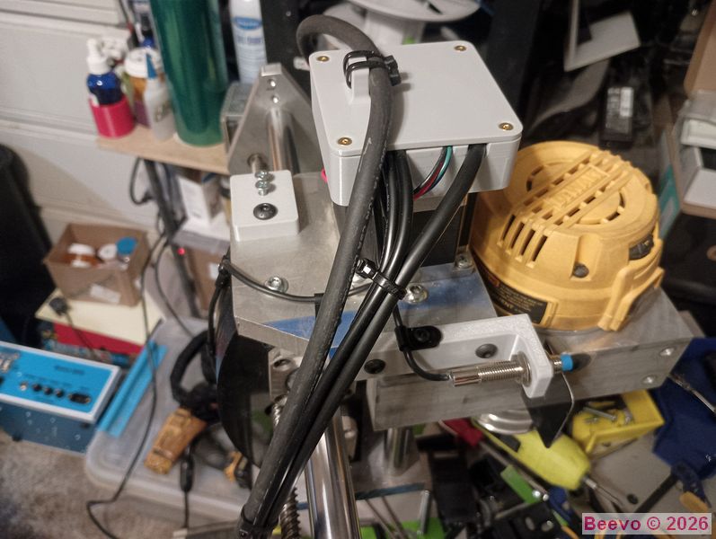
I 3D printed one of my standard project boxes to use as a junction box for the Proximity Sensors (X & Z) and the Z Axis Stepper motor. I designed a basic box with lid and can scale it up/down to suit my needs. Beats the heck out of ordering from Mouser/DigiKey/Amazon and not always finding the perfect size and THEN having to wait for it to show up. The lid is held on with 2-4 machine screws with brass threaded inserts embedded in the body. In this instance I added a boss tot eh lid to secure the router power cord.
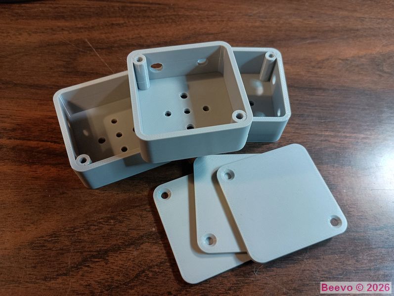
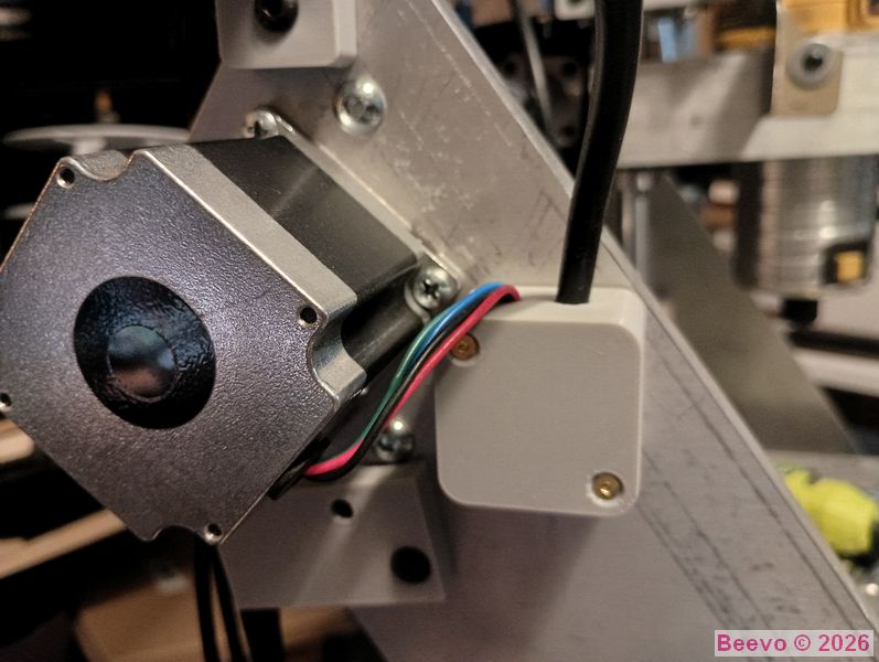
Sample of my 3D printed junction boxes and the X Axis junction box in place. It is SO convenient to make specifically sized enclosures on demand. These take about 20 minutes to print a box and lid.
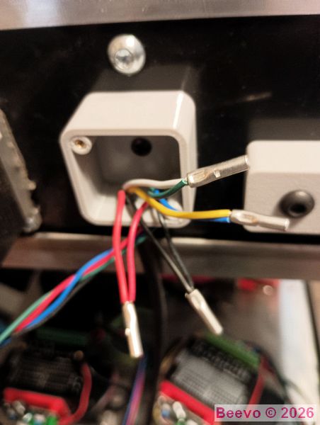
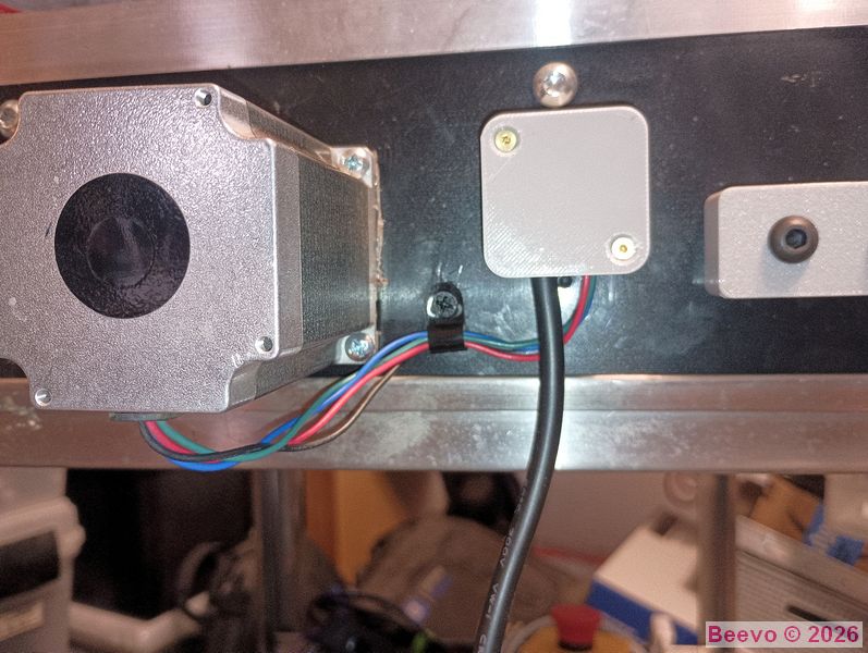
The same approach was used for the wire splicing on the Y Axis Stepper motor.
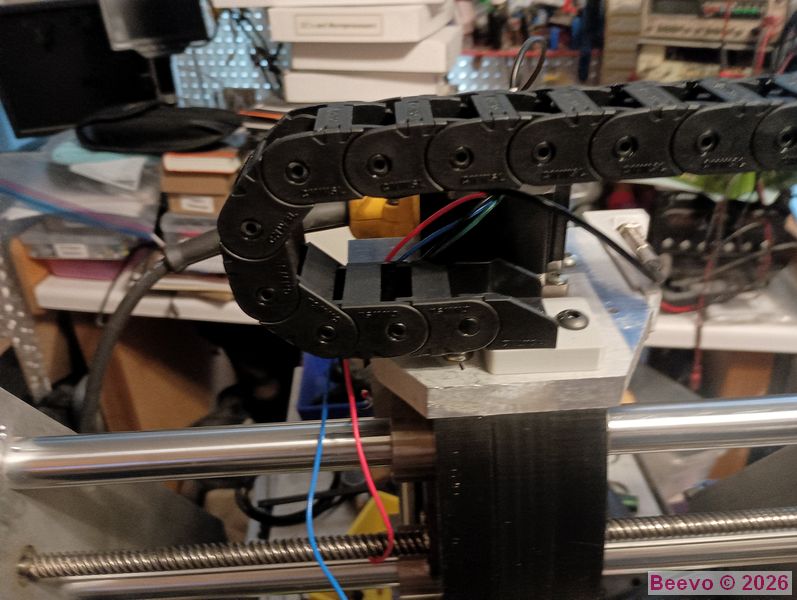
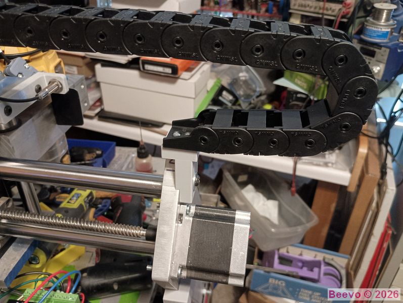
I used 15x20 Open Back drag chain to route all the cables on the machine. This was my first experience with this stuff. Wound up ordering different types without realizing the compatibility. LOL I 3Dprinted the fixed (RH) and movable (LH) brackets and used brass heat set bushings to bolt the chain down. The stepper tester was used to verify the needed length of the drag chain.
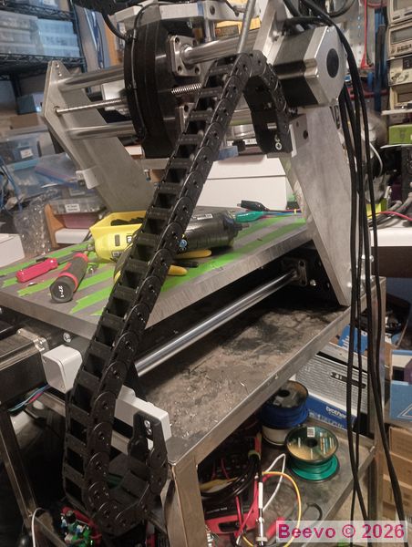
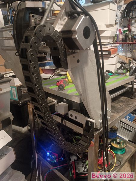
Gantry arm to base drag chain. LH image shows the chain with the Y Axis full forward and full back in the RH image. Attachment brackets 3D printed with brass heat set bushings to secure.
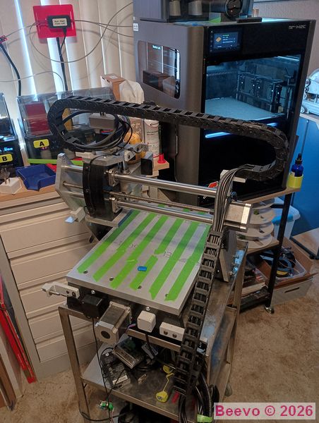
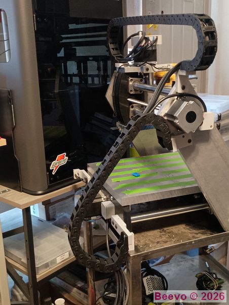
The completed drag chains with the cabling installed.
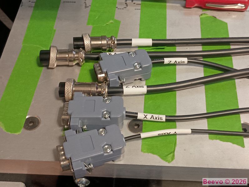
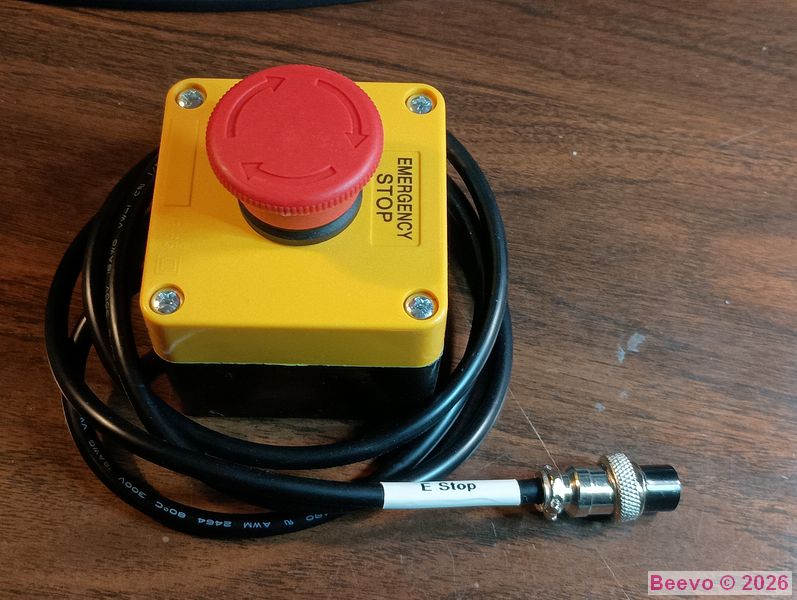
As much as I hate it, I then installed the cord ends for the Proximity Sensors (DE9 d-sub) and Stepper Motors (GX16-5 circular). Then on to the E Stop Switch that uses a GX16-4 circular connector. The Rhino labeler was used to make tubular labels, all of which I remembered to slide over the cord before installing the endfs!