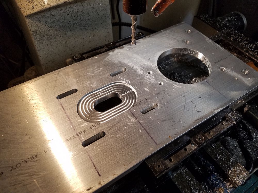
I elected to not try to sandwich the motor mounting plate and drilled and tapped the casting to mount the plate. I had the CNC set up and did not eliminate the pocket and shaft hole for the servo. I only noticed this AFTER I finished the machining.
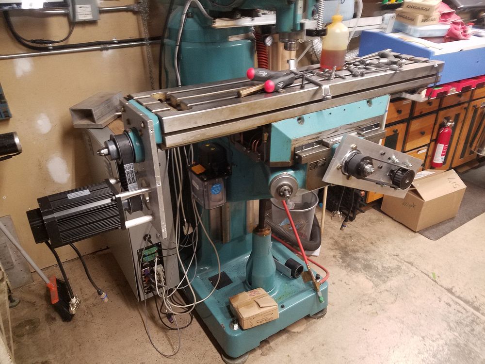
X Axis Drive
I elected to not try to sandwich the motor mounting plate and drilled and tapped
the casting to mount the plate. I had the CNC set up and did not eliminate
the pocket and shaft hole for the servo. I only noticed this AFTER I
finished the machining.
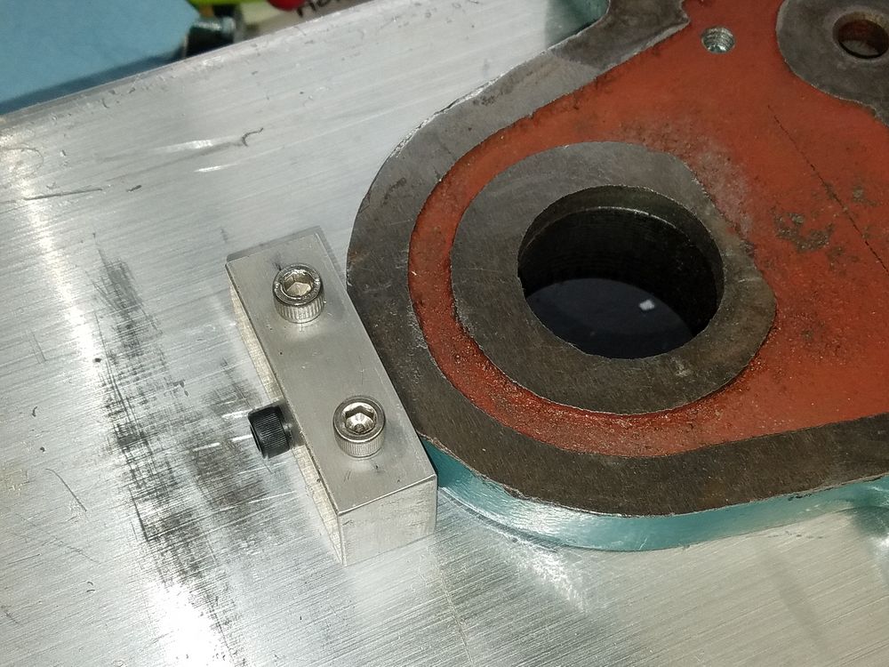
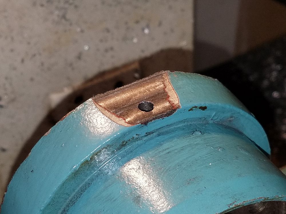
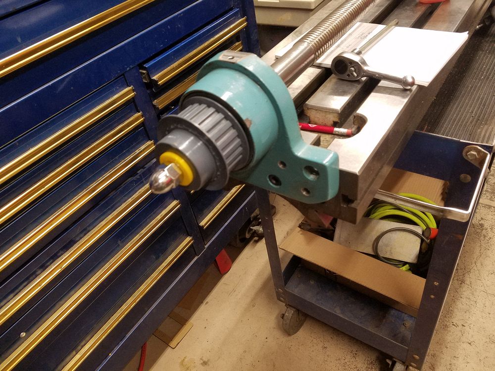
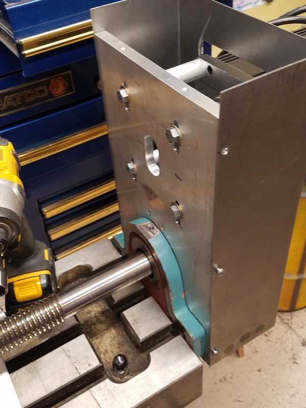
Due to the mass of the motor and the offset of same, I added a tie point on the back side of the bearing casting to prevent vibration and possible breakage. I flat spotted the tip of the casting and drilled and tapped for the block shown in the picture.
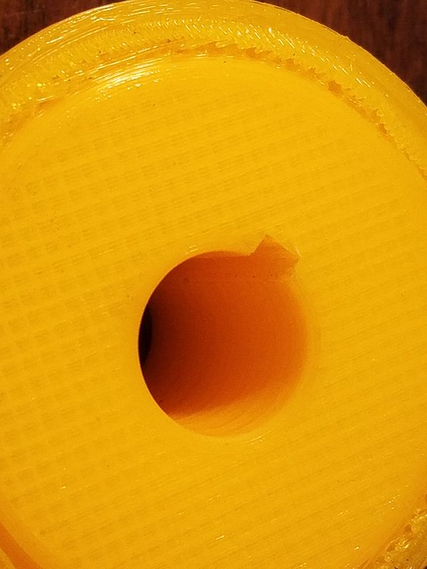
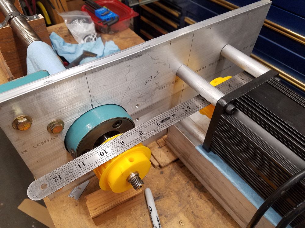
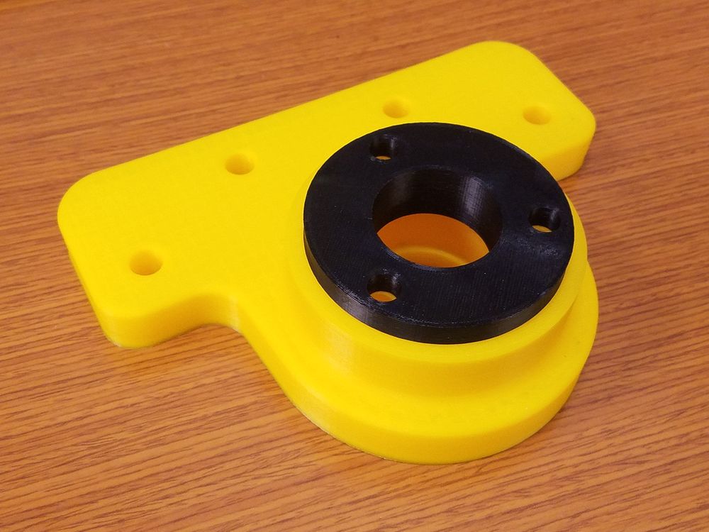
The right image shows setting up the pulley offsets. One very nice thing about McMaster-Carr is you can download CAD files of most parts and in my case I 3D printed some test pulleys. You can even broach a keyway in the test part!
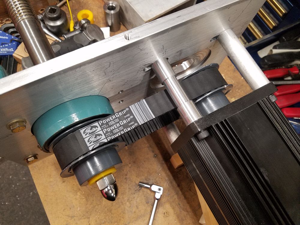
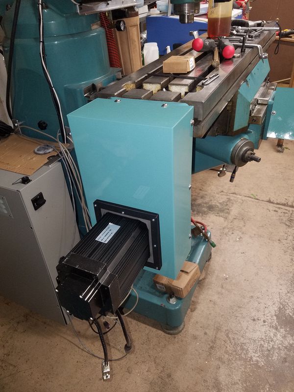
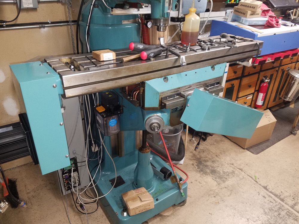
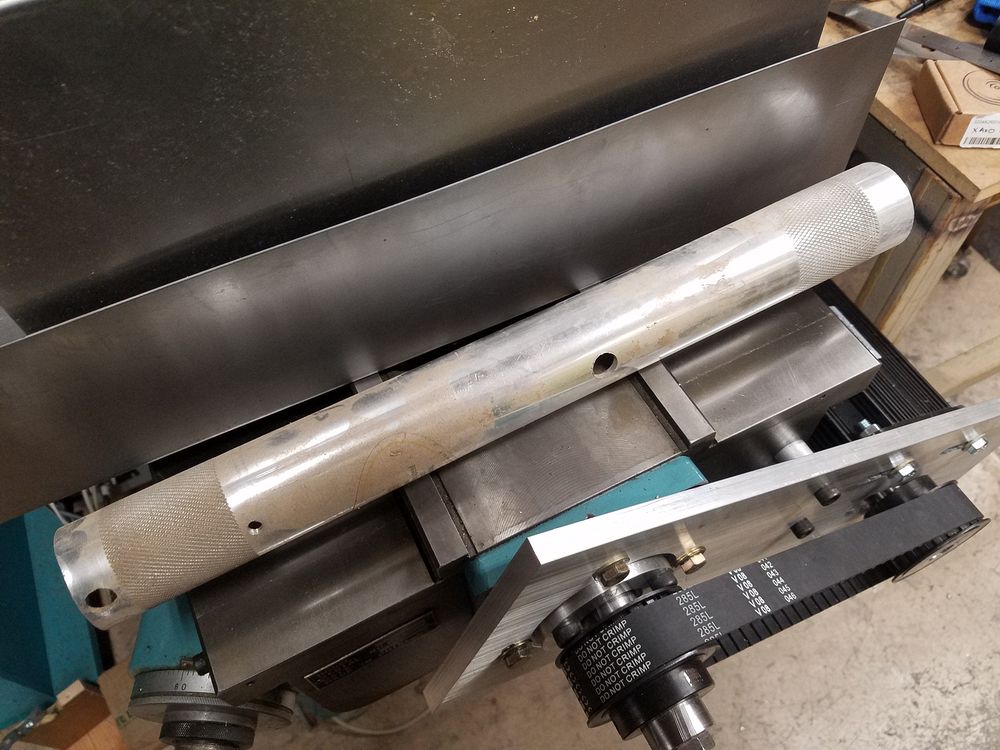
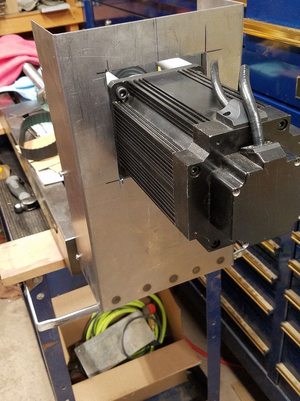
Here is the final setup for the X Axis drive. In this shot I have yet to
make the leaded steel spacers and am relying on some 3D printed spacers. I
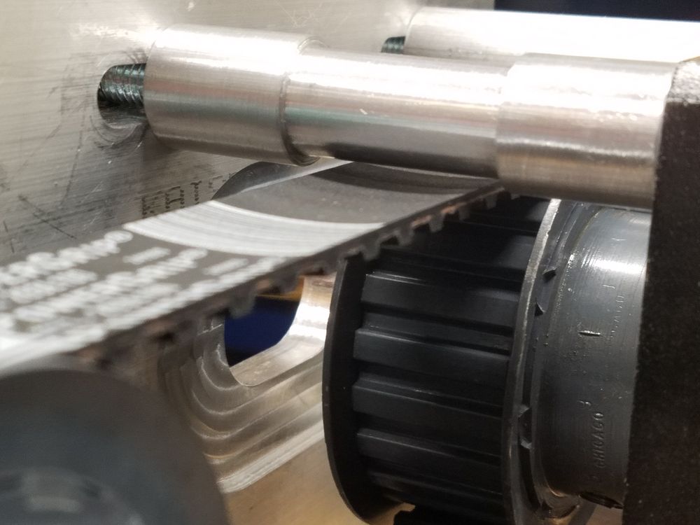
had to machine two of the standoffs to provide clearance to the belt as without
the notch, the belt skimmed the standoff ever so slightly. Unfortunately I
can's test this one until the ball screw is fully installed in the mill and the
table it put back on...
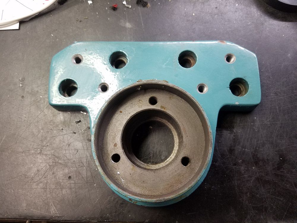
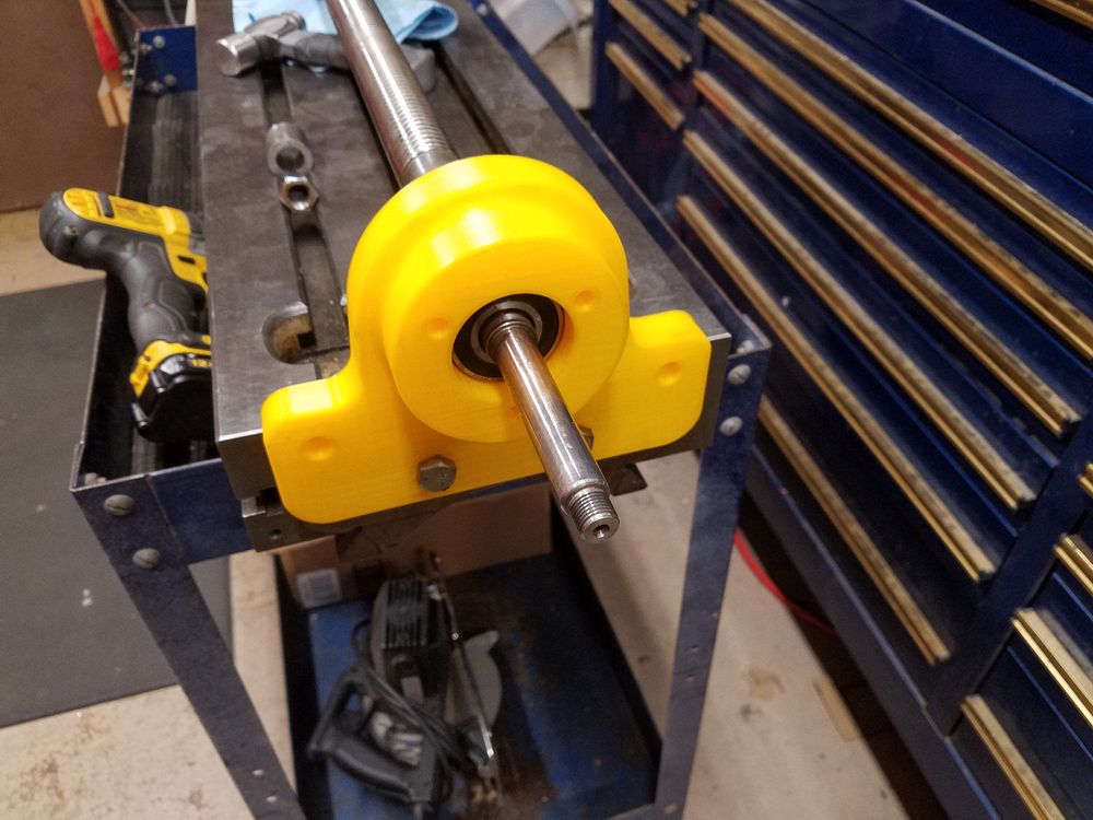
I need to make a bearing mount for the other end of the ball screw as the original was removed when the power feed was installed by Enco when the mill was originally sold. Here is a 3D test part. I decided I can do the final design work for the bearing housing by bolting the bearing plates upside down to the table which is sitting on my roll around until the yoke is completed.
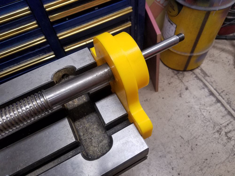
The bearing was pressed into the test housing and installed on the ball screw. Measurements indicate a shim of 0.040" will be needed to space the bearing out from the table.
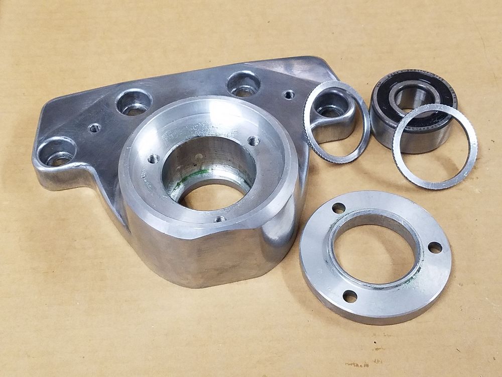
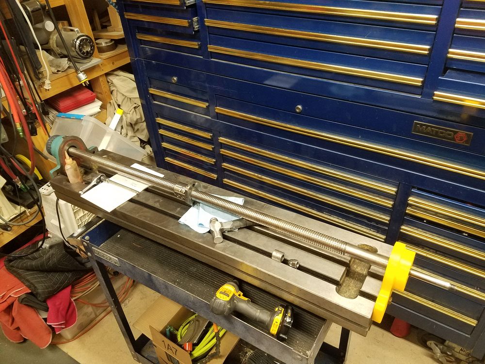
Test part installed. I sourced a Bridgeport "Clone" bearing assembly from eBay (thanks Marty!) and discovered very little in the way of modifications would be required to make it fit my "Clone". I had to slot the four mounting bolts vertically to get the proper alignment. Here's a quick video of the process for one hole. The bearing assembly came with a pair of bearings stacked and I elected to use a single cartridge thrust bearing assembly. The single cartridge bearing was about 3/4 the length of the stacked bearing set which allowed me to move the bearing out from the table by 0.125" that was required to have the face of the casting fit flush on the face of the table.
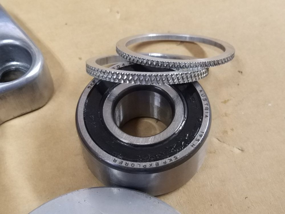
Rooting through the scrap collection (thanks David!) I found an aluminum tube that was formerly part of a trolling motor that happened to be the right size to make spacer rings. The knurled part of the tube was very close to the OD of the bearings and I sliced a couple of spacers. The bearing needed to be moved away from the table face and the thicker of the two spacers went into the casting underneath of the larger single bearing. Due to the reduced height, the thinner spacer went on top of the bearing so the retaining ring would capture the bearing tightly in the correct location. The dual bearing set up also included 4 thin spacers, one of which was used to fine tune the fit.
The four mounting holes had the correct pattern spacing but needed to be moved "up" about 0.125" I accomplished this by merely slotting the mounting holes
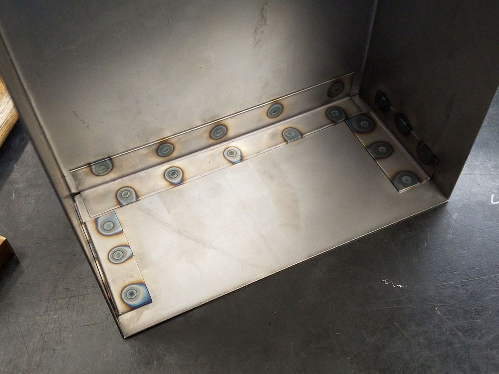
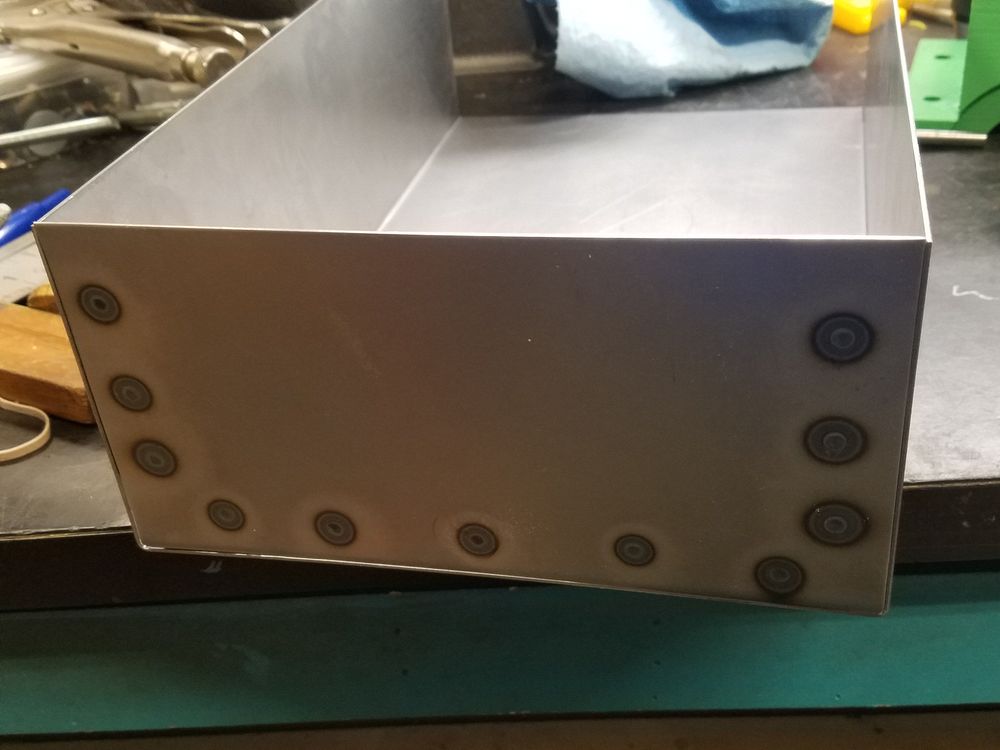
Construction commences on the cover for the X Axis drive. I rarely use, but really love my spot welder.
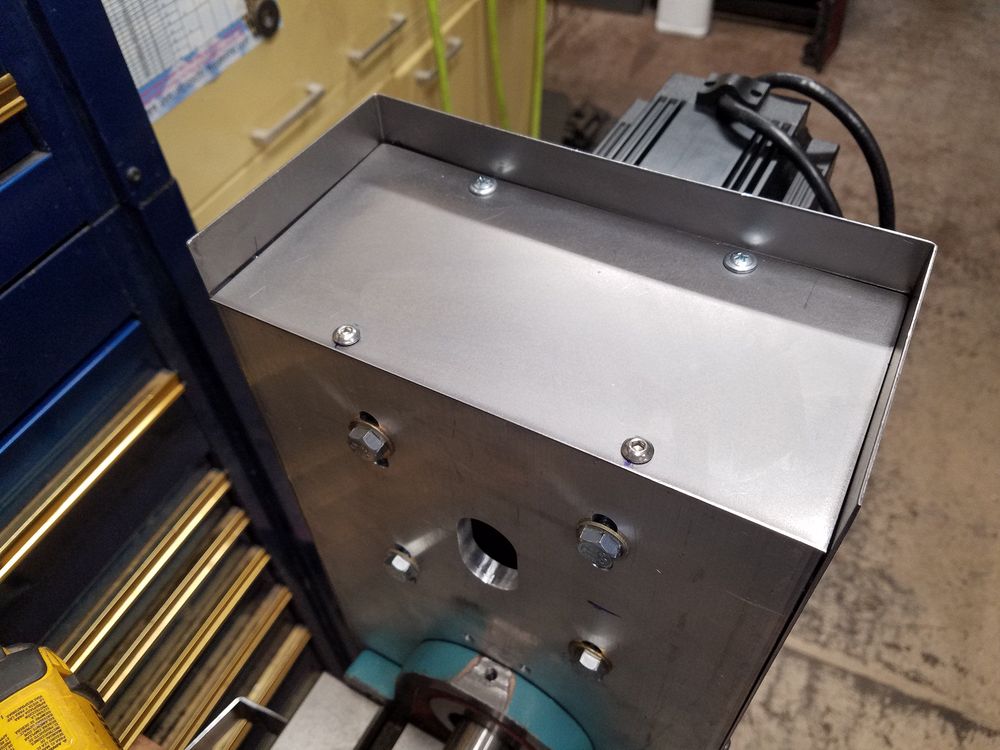
Hole has been hacked in the cover to allow installation around the servo motor. I am going to 3D print a frame to hold a felt gasket to seal the gap. There is enough vertical slot to allow for motor adjustments, though the motor is sitting in the prime location right now. The bottom of the cover will be fabricated next, just wanted to test things first.
I elected to not go through the hell of shortening the cover as the excess length is at the bottom and will not be visible from normal perspectives. A bracket was spot welded to the cover and two sheet metal screws were used to secure. The rest of the bolts to secure the cover are 10-32 SS button head Allen. Starting in on the seal for the motor opening, here is a 3D test print of the frame to hold down the craft foam gasket.
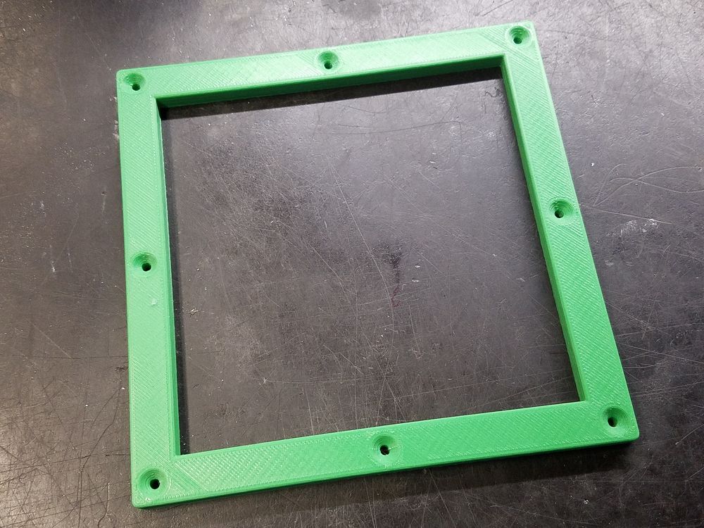
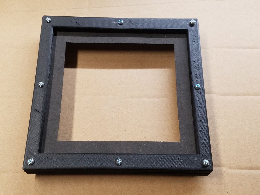
Test print of the gasket frame. I needed to elongate the opening in one direction upon doing a test fit. I printed two frames and sandwiched the EVA Craft Foam gasket between them The laser does a spectacularly good job of cutting this material. The 4-40 machine screws at the corners go through both frames, the gasket and into threaded holes in the metal cover. The side screws are threaded into the rear frame and hold the two frames and the gasket together making for an easier installation.
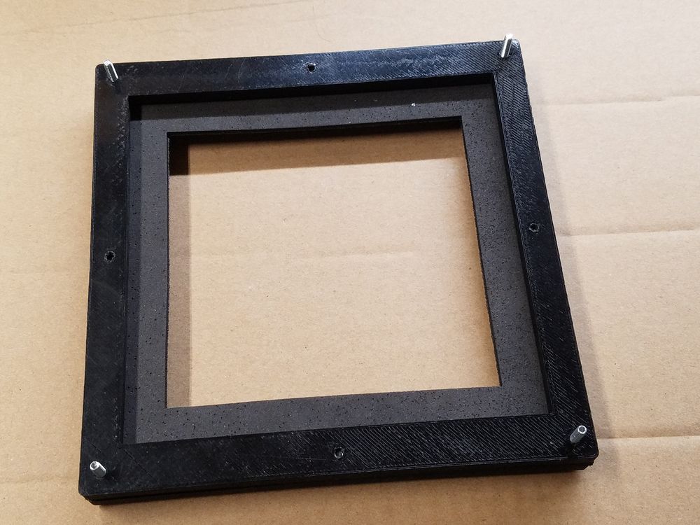
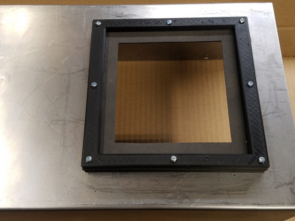
Rear shot of the gasket frame assembly. Right side is a shot of the gasket frame assembly installed on the cover. Due to the cable housing on the motor it will be necessary to install the frame after the cover is installed.